Author - w3badmin

MIG Welding Tips

GMAW – MIG Welding Tips

Getting the Right Weld

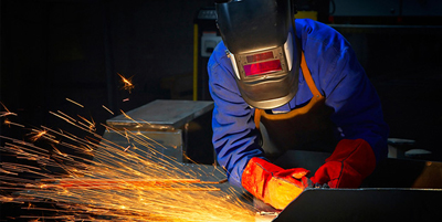
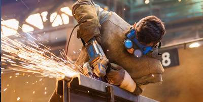
Welding is an essential component of construction and getting the right weld is important to ensure buildings maintain their structural integrity.

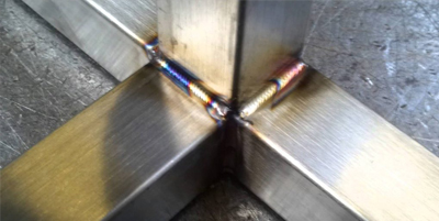
When it comes to gas metal arc metal welding (GMAW) – with the most common type being a fillet weld on mild steel – welders must use the right material and employ the best practice techniques to get the right weld.

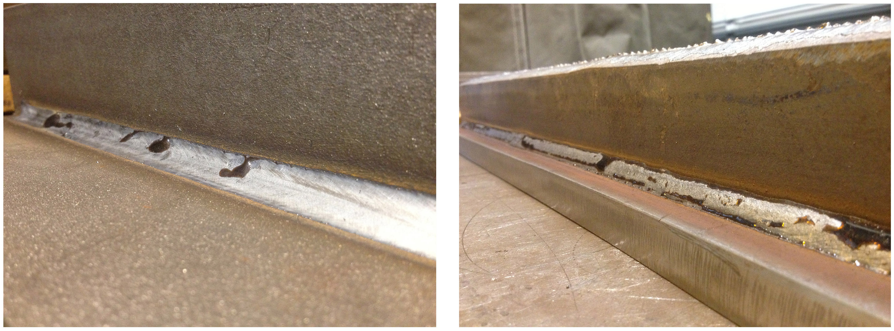
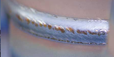
Without proper techniques, weld defects can develop, which slows down production as a result of increased rework and can be costly for operators. Porosity – where gas becomes trapped in the weld metal or along its surface – is one of the major defects that can develop because of poor care and practice, creating a weaker weld. It is caused by a range of factors including contaminated shield gas and unclean base metals.

Weld defects can also be caused by burn-through – when the weld metal burns through the base metal because of excessive heat. Alternatively, minimal heat can cause a lack of penetration which can also lead to weld failure.

Another major welding flaw is undercutting – where a groove forms at the toe of the weld, created by the welder moving too fast. The undercut is usually the thinnest part of the weld, also making it the weakest section.

There are several key steps welders should take before welding to ensure they produce a strong weld, beginning with selecting the right base metal.

Base Metals and Fillers

One of the critical starting points is having the correct base metal. This also incorporates key factors including the type of material, how thick it is and whether it is coated, which could all impact the weld.

It is also crucial to ensure proper preparation of the base material before welding; the surface must first be cleaned with a degreaser and should have minimal gaps.

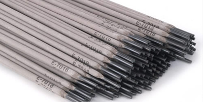
The next phase is selecting the right filler material.

Choosing the wrong wires can affect the strength of a weld, therefore the correct wire must be used to match with a base metal. When considering wires, it is also important to have the right cast – the diameter the wire forms – and the right helix – the height of a wire end when a section is cut of and lay flat on a solid surface. Welding specialists like Welding Industries Australia (WIA) can recommend and provide a wide range of options for arc welding electrodes, metal inert gas (MIG) wires and cored wires for any welding job across a range of industries.

Shielding Gas

It is also important for the correct gas mixtures to be used according to its appropriate application to  minimise weld spatter, ensure weld metal mechanical soundness and optimise penetration profile . For example, when welding mild and carbon steel, a common mixture used across the industry is argon 18 per cent carbon dioxide.

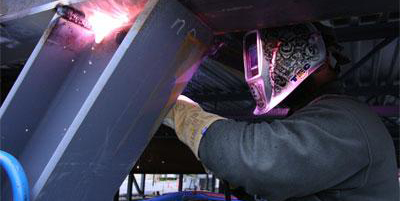
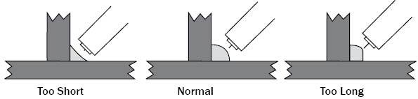
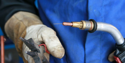
The Right Torch Angle

The torch angle is another critical factor when welding and operators can either use the push or pull method. The push method involves pre-heating the metal and pushing the gun away from the weld puddle. It allows operators to see the direction they are travelling and produces a wider and flatter bead. In contrast, the pull method describes when the torch is angled back at the weld puddle and pulled away from the metal that is deposited, creating a deeper bead.

The neutral position involves the gun remaining perpendicular to the seam.

Maintaining the right torch angle when welding minimises the likelihood of porosity and burn through, boosting efficiency and accuracy. It also reduces the instances of undercutting.

In addition to using the correct torch angle, key factors such as travel speed and amperage must be taken into consideration to produce a proper weld. The higher the amperage, the faster the speed required to avoid creating burn-through. Low amperage, however, creates less heat and requires operators to move slower to minimise fusion flaws.

Welding takes into consideration several factors to ensure operators produce a suitable weld. While the weld may look visually stable, it is also important that the weld is tested to maintain accurate stability.

Read more...

Low-Hydrogen Stick Electrodes: Getting to the Basics

Stick welding is one of the most common welding process. Materials used for structural applications have continued to lend themselves readily to the process, making stick electrodes a prominent choice.

Stick electrodes provide the chemical properties necessary for such applications, along with the low hydrogen levels needed to prevent issues like cracking. They also provide the appropriate mechanical properties for these jobs — most steel used for structural applications requires filler metals that offer 490Mpa of tensile strength. E4918 stick electrodes meet those specifications.

As with any part of the welding process, knowing the basics about E4918 low-hydrogen stick electrodes can help in understanding their operation, performance and resulting welds. We’ve put together some things that should be considered.

Characteristics

E4918 stick electrodes are a good choice for structural steel applications due to their smooth, stable and quiet arc, and their low spatter levels. These applications require careful attention to heat input and are typically on strict deadlines, so it’s important to have a filler metal that gives the welding operator good control over the arc and one that will minimize the need for post-weld clean-up, allowing better productivity.

These stick electrodes also offer good penetration (“medium penetration”) so welding operators who use the right technique can typically avoid weld defects like lack of fusion. They also offer good deposition rates, allowing welding operators to add more weld metal into the joint in a short amount of time. This characteristic is made possible because iron powder has been added to the coating of the stick electrode.

Manganese and silicon (which must be present in specific levels in all E4918 stick electrodes) also provide advantages. These elements work together as deoxidizers to help weld through certain levels of dirt, debris or mill scale that can be commonly found on structural steel applications.

E4918 stick electrodes also offer good arc starts and restarts, which help eliminate issues like porosity at the start or end of the weld. If restriking is allowed, it’s necessary to remove the silicon deposit that forms at the end of the stick electrode to initiate an arc again. Note, however, some welding codes or WPS procedures do not permit the restriking of stick electrodes. Always consult with the specifications for the job beforehand.

Operation

E4918 stick electrodes are designed to operate with power sources that provide an AC or a DC current.

During AC welding, the additional arc stabilizers and/or iron powder within the filler metal coating, makes it possible to maintain a stable arc, even when the power source cycles through the alternating currents (at up to 120 times per second). E4918 stick electrode welds may not be as smooth, because of the continuous changes in the direction of the current.

Alternatively, welding with a DC current can make controlling the arc easier and it can gain a more appealing weld bead because the direction of the current flow is constant.

To gain the best results, follow the manufacturer’s operating parameters recommendations for the given E4918 stick electrode diameter.

Techniques

For an E4918 stick electrode, maintain a good leading angle and “drag” the stick electrode along the weld joint. A 3 to 5-degree angle is ideal for vertical up welding, and employing a slight weaving technique works well in this position. In the flat and horizontal positions, maintain a tight arc length, ideally, keeping the stick electrode almost on top of the weld puddle. Doing so helps minimize the opportunity for porosity.

A good rule of thumb is to maintain a weld bead width approximately two and a half times the diameter of the core wire inside the stick electrode, for flat and horizontal welding applications. For vertical up welding, try to create a weld bead width around two and a half to three times the size of the core wire. Wider weld beads than these recommendations increase the potential for slag inclusions, which compromise the integrity of a structural weld.

Packaging, storage, handling and reconditioning

Because of the low-hydrogen designation of E4918 stick electrodes it is important to protect from moisture damage, it is important to keep that package intact until the products are ready for use. Also keep the stick electrodes in a dry storage area.

Once opened, welding operators should handle the stick electrodes with clean, dry gloves. This will prevent dirt and debris from sticking to the products’ coating and eliminates the opportunity for moisture to be pickup from the welders’ hands. Once opened, stick electrodes need to be stored in an oven at the temperatures recommended by the filler metal manufacturer.

Certain job codes may dictate how long a stick electrode package can remain open on a jobsite and how often the product can be reconditioned in a holding oven — frequent reconditioning can degrade the outer coating and minimize the product’s shelf life. Always consult with the specifications and codes for the requirements on each job.

Read more...

New BlueFX and ViewFX Helmets

Professional Welding Helmets at an Affordable Price

Offering protection, comfort and performance, all at an affordable price, WIA’s new BlueFX and ViewFX welding helmets are packed with exceptional features, coupled with excellent reliability, value for money and WIA’s renowned warranty.

The new BlueFX Auto-Darkening helmet has been designed for welders looking for protection, performance and comfort at an affordable price. Providing the operator with continuous arc sensing capability the BlueFX comes with two arc sensors and has a viewing area of 97 x 46mm. The BlueFX features a high quality shell in a slightly metallic, matt blue colour. Designed with quality in mind the BlueFX comes with a one-year warranty.

The ViewFX is completely new to WIA’s helmet range and has been designed for professional welders wanting extra performance. A step up from the BlueFX helmet, the ViewFX comes standard with four arc sensors and has an extra wide 97 x 60mm viewing area, giving operators a greater view of the weld. The ViewFX shell is high quality and durable, and comes in a metallic matt grey colour. Reliable and dependable, the ViewFX comes standard with a two-year warranty for extra peace of mind.

Both helmets are impressive and suitable for all general welding applications, including stick, MIG and TIG welding plus plasma cutting, and come standard with a grind mode, meaning users only need one helmet for all their welding requirements – including weld preparation and clean-up.

Battery powered with solar assist, the helmets also offer exceptionally long life before charging is required. Delivering up to 1500 hours of interruption free welding with MIG, Stick, TIG and Plasma power sources, the helmets are always ready to go. As well as the lithium battery being replaceable, the helmets also feature gold contacts on the battery terminals, to ensure dependable contact, an auto on/off function and a low battery indicator.

The helmets’ lenses automatically switch from light state 4 to adjustable welding shades 9-13 whenever an arc is struck, and extremely quickly. The lens darkening reaction time is a lightning fast 1/12,000 sec for the BlueFX and 1/15,000 for the ViewFX. Then after welding, the dark to clear state speed of the lens can be easily adjusted from 0.1 sec to 1.0 sec for maximum control when welding. This feature is found to be very useful in eliminating bright rays often present in high amp applications.

The helmets also feature an innovative sensitivity control which makes the lens more responsive to different light levels in various welding processes. Users have found that the midrange or 30-50% sensitivity setting is their preference for most applications.

For extra view of the weld both helmets also come with a built-in provision for a magnifying lens, if needed.

Designed with operator comfort in mind, the helmets feature high quality, lightweight headgear (510g for the BlueFX and 550g for the ViewFX). In addition, the headgear is fully and easily adjustable providing welders with maximum face and neck protection.

Tested in Australia, the lens and helmet comply with Australian Standards and have a high impact rating. AS/NZS 1338.1 (Auto-Darkening) and AS/NZS1337.1 B (High Impact).

And like all WIA products, these helmets are manufactured with quality and longevity in mind providing warranty for peace of mind.

Read more...

How to Fix 8 Common Welding Problems with these Easy Steps

Welding is defined as a process where two or more pieces of metal or thermoplastics are fastened together by use of heat and pressure. The process of welding that is used depends on a variety of factors but the form and thickness of the material is usually the deciding factor for which method is most effective . Some of the most common types of welding today are Metal Inert Gas Welding (MIG) or Gas Metal Arc Welding (GMAW), Arc Welding or Shielded Metal Arc Welding (SMAW), Tungsten Inert Gas (TIG) or Gas Tungsten Arc Welding(GTAW) and Flux-Cored Arc Welding (FCAW).

Over the years, these welding techniques have been simplified with superior welding equipment.  With such equipment, it is possible for many operators to forget essential steps when performing the weld. However, when these same operators run into trouble, they are unable to diagnose and correct problems. Here are some common welding issues and how to correct them.

1. Spatter

In gas metal arc welding (GMAW) a common unwanted side effect is the creation of what welders call spatter. These are droplets of molten material that are produced near the welding arc. Spatter happens when welding currents are too high, incorrect polarity or if there is insufficient gas shielding. In order to avoid spatter, the reduction of the welding current and arc length is recommended. In addition, the welder can check to see if there is the correct usage of polarity for the consumable. Last, it is a good idea to check the shielding gas type and flow rate, as well as clean the gas nozzle and increase the torch-to-plate angle.

2. Porosity

Porosity is caused by the absorption of nitrogen, oxygen and hydrogen in the molten weld pool which is then released on solidification to become trapped in the weld metal. Causes for porosity include the presence of moisture, rust, grease or paint on the plate edges, insufficient gas shielding, or when the welding is done onto small gaps that have air in between. To avoid porosity in a weld, the welder should re-bake or use fresh welding consumables and check the welding torch for leaks. Having dry and clean plate edges helps too. It would also be a good idea to check the shielding gas type and flow rates, clean the gas nozzle of the welding device and make sure the torch to plate angle is not too large or small.

3. Undercut

Undercuts occur when the arc voltage is too high or when the arc is too long. It can also happen if there is incorrect electrode usage or angle, or if the electrode is too large for the thickness of the plate. In addition, undercuts tend to happen if the travel speed is too quick. Besides watching the speed, it is important to check for proper manipulation of the electrode used. It is recommended that welders do not use a bigger than needed electrode because if the amount of molten metal becomes too big, there will be undercut. Next, it is essential to look after how much weave is used as well. Last, do not hold an electrode near the vertical plate when making a horizontal fillet weld.

4. Deformation

Deformation happens during the contraction of welded metals when it is cooling and hardening. This occurs if the welding sequence is not suitable for the intended weld, there are too many thin beads, poor plate fit-ups (insufficient clamping) before welding. Some good solutions to avoid deformation are to weld from both sides of the joint, welding from the centre out (in opposite directions), using a larger electrode and clamping firmly. Changing the sequence of welds, or the location of the joint, or making fewer passes, can also help reduce
the risk.

5. Cracks

In any sort of construction, every crack (regardless of size) is considered a defect. It can be dangerous because small cracks have the potential to become larger over time. It is not as simple as filling the gap with material because cracks need to be ground out and then a new weld is performed to correct the error. Since this is tedious, prevention is preferable than the cure. To avoid cracks, it is necessary to spend time grinding, cleaning, filing or deburring the edges of the plates so they easily fit together. It would be a good idea to reheat both sides of the joint since having the right temperature matters and clamp the plates together. And before going on to weld, check to see if you have the right amount of heat dialled up by testing your machine settings .

6. Incomplete Penetration and Fusion

Incomplete root fusion is when the weld fails to fuse on one side of the joint in the root. Incomplete root penetration occurs when both sides root region of the joint are unfused. These issues tend to happen more in consumable electrode processes (MIG, MAG, FCAW, MMA and SAW) where the weld metal is ‘automatically’ deposited as the arc consumes the electrode wire or rod . Solutions include the use of wider root gap, electrodes whose diameter size is approximately the gap width of the root. When welding, it would be good to use lower travel speed and weave between the plate edges.

7. Slag Inclusions

Slag inclusion is the small particles of flux that become trapped in the weld metal, which prevent complete penetration of the weld . The way to prevent this is to have well maintained flux-coated consumables . Having the correct current, voltage and good arc characteristics would be necessary to ensure quality welds with complete fusions when running through.

8. Incorrect Wire Delivery

When welders start hearing a chattering sound within the gun cable, there could be an issue with the wire delivery system. In this instance, this is always to do with ensuring the correct set up of the equipment and maintenance. Sometimes, welders make the mistake of using tips that are too large for the application that can lead to some of the other welding problems listed above. Some tips include ensuring that the contact tip of the gun is properly functioning and double checking the size of the wire that will be used. It is a good idea to check the tip of the wire to see if it is worn out and needs to be replaced. As for the drive rolls, it is worth checking them as they do wear out. Always make sure that the drive rolls and guide tube are within close proximity.

The importance of the best equipment

At the end of the day, having the proper knowledge on avoiding welding pitfalls and having the best and latest welding equipment with the most up to date technology does make a difference when it comes to lessening the chances of having defects happening. Thus, having reliable suppliers who are renowned for their product excellence, such as Welding Industries Australia (WIA), is essential for businesses that depend on welding as part of their core business structure.

Read more...

Austarc 16TC – Why It’s Australia’s Best Selling Electrode

With so many electrodes on the market, selecting the right one for the job can be challenging. Choosing poorly can result in increased spatter levels, cracking and an overall problematic welding technique.

Welding Industries of Australia’s (WIA) Austarc 16TC, Australia’s number one best-selling electrode, features reduced spatter levels, high operator appeal and a low hydrogen classification. Find out why the 16TC is the electrode of choice for professional welders across Australia.

Uniquely Manufactured

A major challenge for welders when using electrodes is their difficulty to start and operate. The main cause of this is the materials that are used in the manufacturing process.

Manufactured in New Zealand, the Austarc 16TC differs from other electrodes in that it is twin-coated.

Twin-Coating

Typically, with low hydrogen classification electrodes the ingredients used in the flux coating make the electrode difficult to start, run and operate.

This is where the Austarc 16TC stands out from other low hydrogen electrodes.

The 16TC twin-coating manufacturing process puts the ingredients that make the electrode difficult to start and run in the outer coating, leaving the arc friendly ingredients in the inner coating. It is this unique feature that results in the 16TC being the smoothest and easiest to run electrode on the market.

High Operator Appeal

Not only is the Austarc 16TC the electrode of choice for professional welders, but many young aspiring welders begin their welding career using the Austarc 16TC.

As the Austarc 16TC is much easier to operate than electrodes of the same classification, Australia’s leading colleges and welding schools use the electrode in technical exams.

The operator friendly features of the Austarc 16TC gives the students a higher chance of passing their exams and makes the welder familiar with the best-selling electrode from day one of their welding career.

Versatility

Suited to almost all welding positions, the 16TC is conveniently manufactured in a variety of weights and sizes and is commonly found in many different sectors, including construction, maintenance, repair, structural and fabrication.

A further issue with low hydrogen electrodes is that they usually require more power to initiate. An additional benefit of the twin-coated design of the Austarc 16TC is its ability to function when there is a limited power supply, for example in rural areas, where many other branded electrodes struggle.

Low Spatter Levels

A common issue in arc welding is the occurrence of spatter. In all welding operations a key priority is to limit post-weld clean up time by reducing the amount of spatter.

Poor quality welding electrode causes increased spatter levels. To limit spatter levels the Austarc 16TC is manufactured using only the highest quality materials.

This includes a 100% steel core. The high purity of the Australian steel delivers a deposited weld metal that is cleaner and free of impurities. Leading to a tidier, stronger and more reliable weld.

In addition, by increasing the ease of operability, the Austarc 16TC is designed to get the most out of welders by enhancing their technical ability, leading to a more accurate weld.

The Welding Experts

WIA has been supplying the Australian welding market for more than 50 years. Trusted by the very best, WIA has a dedicated team of technical experts on hand to advise and assist all of its customers.

Since its development in the 1960s, the Austarc 16TC continues to be the number one best selling electrode in Australia. The twin-coating technique has often been imitated but no one has come close to producing an electrode that is as easy to operate as the Austarc 16TC.

Relied upon across Australia’s entire welding industry, the Austarc 16TC remains the leading electrode of choice.

Read more...

Understanding Deoxidizers in Filler Metals

While they make up only a small part of the upfront cost in a welding operation, filler metals are a key component in achieving high quality and productivity — and they can significantly impact the bottom line.

Which filler metal is best for an application depends primarily on how the finished weld will be used and/or the service conditions it will encounter. Does the weld need to withstand high temperatures? Is toughness, strength or ductility the main priority — or are all three important? Filler metal manufacturers can formulate their products with elements to achieve these mechanical properties and, at the same time, reduce potential costs for rework by ensuring a high-quality weld the first time.

The addition of deoxidizers in filler metals can minimize costs by lessening the need for non-value-added activities such as pre-weld cleaning and grinding. This allows welding operators to spend more time welding, generating higher levels of productivity and profit.

Added deoxidizers in filler metals allow welding operators to weld over oils, rust, mill scale and similar contaminants commonly found on heavy-scaled plates such as hot-rolled steel used in structural applications — without the need to grind or clean before. By minimising a pre-cleaning step, companies can save the cost of not only labour, but also the expense for grinding equipment purchases and maintenance, and for purchasing and inventorying grinding wheels.

Added deoxidizers in filler metals can minimise the pre cleaning step and allow welding operators to weld over oils, rust, mill scale and similar contaminants commonly found on heavy-scaled plates such as hot-rolled steel used in structural applications — without the need to grind or clean before.

Filler metals with added deoxidizers also allow companies to use less expensive base materials, as steel that goes through extra processing to remove mill scale ahead of time costs more.

The elements

Deoxidizers work by acting as scavengers that combine with oxygen and then, as the weld metal cools, they diffuse with the oxygen to the surface of the weld. This action allows the filler metal to weld smoothly through mill scale or rust without compromising arc quality or welding performance, and without concern of inclusions in the completed weld.

There are three primary elements that manufacturers use as deoxidizers: manganese, silicone and aluminium. Occasionally they also use titanium or zirconium.

Manganese, along with providing reliable deoxidizing capabilities, also increases strength in the completed weld. There are some health concerns around the addition of manganese, however, so it is important to have proper weld fume management in place such as a weld fume extractor or powered air purifying respirator (PAPR). There are also low manganese flux-cored and metal-cored wires available in the marketplace to address safety and compliance concerns associated with manganese exposure in weld fumes.

As an added deoxidizer, silicon also provides good weld metal fluidity so that the filler metal wets into the toes of the weld for complete fusion and produces a smooth, flat weld bead. Depending on the type of filler metal, there may be more or less silicon in it; the more there is, the more fluid the weld pool will be. Upon cooling of the weld, the silicon will rise to the surface in the form of small silicon islands or silicates that can typically be removed easily with a wire brush. Silicates are formed when silicon, manganese, iron and oxygen combine. These are prevalent in metal-cored wires, such as those classified as American Welding Society (AWS) E70C-6M H4.

Aluminium is most often used as an added deoxidizer in self-shielded flux-cored wires to aid in slag formation. However, too much aluminium in a filler metal can make the weld brittle because the higher the content of this element, the more limited the low temperature toughness is. In general, filler metals with high amounts aluminium do not typically offer much, if any, impact toughness.

Deoxidizers act as scavengers that combine with oxygen and then, as the weld metal cools, they diffuse with the oxygen to the surface of the weld.

Although they do not contain an internal flux of elements like metal-cored or flux-cored wires do, solid wires are also available with added deoxidizers. These come in the chemistry of the “green rod” or raw materials used for the wires. AWS ER70S-6 wires tend to have slightly more deoxidizers than other solid wires, except for ER70S-2 wires. The difference is that the latter has lower levels of manganese and silicon, and use titanium and zirconium to help maintain strength.

Other considerations

Typically, the specifications for a given welding application will indicate which AWS classification of wire is needed. Within that classification, manufacturers may add varying amounts of deoxidizers, which impact the performance characteristics of the filler metal. Some welding operator preference comes into play as one wire may perform slightly better than another of the same classification.

Different gas mixtures can also impact on how filler metals with added deoxidizers behave. Higher argon mixes with lower amounts of CO2 tend to operate better with filler metals that have high levels of deoxidizers and can help lower the silicate formation. For example, gas mixtures that are 75 percent argon and 25 percent CO2 offer a higher silicone formation compared with a mixture that is 90 percent argon and 10 percent CO2 for a given base material. Similarly, gas-shielded flux-cored wires with added deoxidizers tend to offer better weldability and a more stable arc than a self-shielded flux-cored wire with the same amount, particularly when paired with a shielding gas with lower CO2 levels.

Base material condition affects the amount of silicon island formation in a completed weld — a clean plate (left) generates fewer islands, while a plate with mill scale creates more. These can typically be removed easily with a wire brush.

Regardless of the type of filler metal used — solid, metal-cored or flux-cored — selecting one with added deoxidizers could positively impact the efficiency and cost savings in a welding operation, while also providing the quality needed. Take care to find the product that offers both the performance and mechanical and chemical properties needed to gain the best results.

Read more...

Miller Digital Elite Auto-Darkening Welding Helmets

Exclusive X-Mode Technology!

With so many different welding helmets on the market, selecting a welding helmet isn’t always easy. If you’re a professional welder and serious about welding protection, performance and comfort, there are a few things to look for.

Not all welding helmets are the same. It’s important to consider differences in weight, switching speeds, the number of arc sensors, the quality of the lens and of course comfort.

The Miller Digital Elite is a premium offering, designed for industrial welding applications. It’s suitable for a variety of welding applications, including MIG, Stick, TIG, plasma cutting, flux cored and pulse welding.

Suitable for all stages of welding, the Digital Elite offers variable shade control and 4 modes:

  • Weld – For all welding applications
  • Cut – For plasma, laser, gas welding and cutting applications
  • Grind – For preparation and clean up
  • X-Mode – Electromagnetic arc sensing technology

Exclusive to Miller’s Digital Elite series X-Mode ensures that the lens will only darken when an arc is struck. If you weld outdoors, at low currents, in areas effected by low hanging fluorescent or strobe lights, or in positions that can obstruct the lens, X-Mode is the answer. No more flickering!

When it comes to headgear, the Digital Elite offers a lightweight one that has multiple settings, allowing operators to achieve the best fit and comfort. Weighing only 510g, the helmet is lighter than others and can be worn for longer periods, keeping operator fatigue to a minimum.

With 4 arc sensors, the Digital Elite helmet provides continuous arc sensing for the most demanding applications.

Fitted with an auto-darkening lens, the Digital Elite helmet provides visibility even when welding has stopped. When inactive the lens is usually set to shade 3 or 4, which is relatively easy to see through, then when an arc is struck, the lens automatically darkens lightning fast – 1/20,000 of a second, to shade 8 to 13. After welding, the dark to clear state speed of the lens can be easily adjusted from 0.1 sec to 1.0 for maximum control when welding.

For a better view, the Digital Elite helmet comes with a built-in magnifying lens provision, so you can get a much closer view of the workpiece.

Battery powered with solar assist, the helmet also offers an exceptionally long life before charging is required. Delivering up to 3000 hours of interruption free welding.

Tested in Australian the Miller Digital Elite helmet complies with Australian standards AS/NZS 1338.1 (Auto-Darkening) and AS/NZS 1337.1 B (High Impact).

Manufactured with quality and longevity the Digital Elite comes with a 3 year warranty (Auto-Darkening lens only) for peace of mind.

If you’re serious about welding protection, visit your nearest stockist and take a serious look at the Miller Digital Elite Auto-Darkening helmet. Available in black or a range of graphics, choosing one will be something you won’t regret

Read more...

Eight Tips for Creating a Good Weld

Eight tips for creating a good weld

It’s important to know the basic principles to creating a safe, strong and clean weld.

Mathew Hefferan, Field Applications Specialist at Welding Industries of Australia (WIA) shares his top eight tips to create a good weld.

1. Safety

Make sure you have the correct safety equipment, including gloves, a fire-resistant jacket and a helmet.

Designed for the welder who wants protection, performance and comfort at an affordable price, WIA offers the BlueFX & ViewFX auto darkening helmets making it easier for welders to remain safe.

2. Select a process

MIG, Flux Cored, Stick and TIG? Don’t get confused by all the different terms.

Wire welding uses spools of wire fed through a gun, and the constant feed of wire minimises starts and stops. It’s fast, more economical and better suited to welding thin sheet metal.

There are two types of wire welding:

1. MIG (metal inert gas): MIG welding relies on a constant stream of shielding gas to protect the weld from contamination. The limitations to MIG welding are that it can be difficult to use outdoors, and you have to cart around the gas bottle.

2. Flux-cored: Flux-cored welding uses wire that is specifically designed for use with or without shielding gas depending upon the wire being used. Self-shielded wires that can run without the use of gas are suited to outdoor work.

Stick (SMAW)

The best choice for quick repairs. It’s easy to set up and it uses a stick electrode like Austarc 16TC and 12P, so you don’t need a wire feeder. Stick is slower than MIG welding, but often more forgiving when working with dirty or rusty metal. Stick is not recommended for thin sheet metal welding.

Tungsten Inert Gas (TIG)

TIG welding is preferred for architectural or automotive work where the weld has to look good. It’s also a good way to weld thin and sheet metal and achieve a seamless look. TIG is the hardest to learn, but it’s not out of your grasp if you put the effort into it. TIG machines can weld a variety of metals, however if you want to specifically TIG weld aluminium then the a machine with AC/DC capabilities is required, for example the WIA Weldarc 200i AC/DC machine.

If your work requires using a range of different processes, WIA offers various multi-process machines including the Weldmatic 200i, 250i, 350i or 500i.

3. Select the right machine for your weld

There is no single welding process that suits all applications, so you’ll need to choose one that best matches your welding application.

During the selection process the following factors should be considered:

  • type of material being welded
  • thickness of the material
  • the welding position
  • type of welding power source and the amount of current available

To help make the selection process a little easier, WIA have put together a selection to assist you in selecting the right welder for your application.

4. Ensure your material is clean

Make sure all the materials are clean. Any oil, rust, paint or mill scale can cause contamination and will result in a poor weld. Before you start the welding process, brush all your equipment, surfaces and materials down to ensure everything is clean.

5. Select the correct settings

Having the correct settings on your welding machine will place a huge impact on the quality of your weld. Every WIA product comes with a product data sheet that will enable you to determine the optimum settings for your weld.

6. Maintain the correct stick out

When MIG welding, it’s important to maintain the correct CTWD contact tip to work distance. If your CTWD is too close, you will find excessive tip wear and if the CTWD is too far, you will experience a reduction in amperage. Both issues will result in a poor weld.

The optimum CTWD for a 0.9mm wire is 10 to 16mm and for a 1.2mm wire is 16 to 19mm.

7. Adjust your machine for every weld

Check your reference chart and adjust your wfs and voltage to suit. Make several practice welds on some scrap metal to ensure you are happy and comfortable with the settings.

8. Practice, practice, practice!

Practice makes perfect. The more welding you do, the better you will become.

Read more...

Avoiding Common Flux-Cored Wire Problems

Like every other welding process, flux cored welding comes with some challenges, but with some know-how and a bit of practice, you can prevent some of the common problems and gain the weld quality you need.

To help we’ve put together some tips associated with common undercutting, lack of fusion, slag inclusions and penetration problems.

Undercutting

The problem

Undercutting causes a weaker area at the toe of the weld and often leads to cracking.

The solution

  • Use the proper welding current and voltage and adjust to the right gun angle.
  • Maintain a travel speed that allows the weld metal to fill the melted-out areas of the base metal completely, or if you are using a weaving technique, pause at each side of the weld bead.

Lack of fusion

The problem

Failure of the weld metal to fuse completely with the base metal.

Solution

  • Obtain the correct angle – place the stringer bead in its proper location at the joint, adjust the work angle or widen the groove to access the bottom during welding as needed.
  • Keep the arc on the trailing edge of the welding puddle and maintain a gun angle drag of 15 to 45 degrees. If using a weaving technique, momentarily hold the arc on the groove sidewalls when welding.
  • Increase your voltage range and/or adjust the wire feed speed as necessary to obtain complete fusion. If you feel that the wire is getting ahead of the work puddle, simple adjustments, such as increasing travel speed or using a higher welding current, can prevent problems.
  • Clean the surface of the base metal prior to welding to remove contaminants to prevent lack of fusion.

Slag Inclusions

Slag inclusions occur when the slag generated by the molten flux in the wire’s core becomes trapped inside of the weld. There are four major causes of slag inclusions.

Incorrect weld bead placement

Provide sufficient space in the weld joint for additional passes, particularly on joints requiring multiple passes.

Travel angle

Maintain the correct travel angle and travel speed. In flat, horizontal, and overhead positions your drag angle should be between 15 and 45 degrees. In the vertical up position, your drag angle should be between 5 and 15 degrees. If you still experience slag inclusions increase your drag angle slightly. Maintain a steady travel speed; if you travel too slowly, the weld puddle will get ahead of the arc and create slag inclusions.

Incorrect weld heat input

Maintain proper weld heat input, too low of welding heat input can cause slag inclusions. Use the manufacturer’s recommended parameters for a given wire diameter. If slag inclusions still occur, increase the voltage until the inclusions cease.

Contaminants

Clean thoroughly between weld passes, removing any slag with a chipping hammer, wire brush or grinding before beginning your next weld pass.

Excessive or Lack of Penetration

The problem

Excessive penetration occurs when the weld metal melts through the base metal and hangs underneath the weld. It often results from too much heat.

The solution

  • Select a lower voltage range, reduce the wire feed speed and increase travel speed.
  • Selecting a higher wire feed speed, a higher voltage range and/or reducing travel speed can prevent problems like lack of penetration.
  • Prepare the joint to permit access to the bottom of the groove, while also maintaining proper welding wire extension and arc characteristics.

Using these valuable tips should result in good welding technique, and your ability to prevent these problems—or identify and rectify them quickly without sacrificing time or quality.

Read more...

Is Metal Cored Wire the Right Choice?

Is Metal Cored Wire the Right Choice?

Companies are always looking to improve productivity and gain an edge, while still keeping costs low and producing high-quality parts. There are a number of solutions that can help companies reach these goals — from investing in more efficient equipment or welding processes, to improving workflow.

The ability to reduce or eliminate the time spent on certain tasks during the welding process — such as cleaning, applying anti-spatter, removing spatter and slag, and post-weld grinding — can provide significant productivity and efficiency benefits.
In the right applications, metal-cored wire is among the solutions that can provide productivity and time-saving benefits. There are some key steps that can help determine if metal-cored wire is the right choice.

Behind the technology

As with any type of filler metal, metal-cored wire has its own specific characteristics, benefits, limitations and best-suited applications. Because metal-cored wire is a hollow metal sheath filled with metallic powders, alloys and arc stabilizers, it can create distinct results. These include lowering oxidation, providing higher impact strengths and reducing silicon depositions. These characteristics also make metal-cored wire especially suitable for welding through mill scale.

When welding with metal-cored wire, the spray transfer process is used. This process creates tiny filler metal droplets that deposit in the weld puddle and generate little to no spatter. Because the current travels through the outside metal sheath, the wire produces a broad, cone-shaped arc. This results in a wider penetration profile compared to the more finger-like penetration of solid wire. This arc shape also creates a wide, consistent bead profile that bridges gaps easily and accurately without burn-through.

The construction of metal-cored wire also allows for greater travel speeds and deposition rates, and helps minimize porosity and undercut in the final weld. All of these factors can increase productivity and allow welding operators to weld more efficiently, deposit more weld metal, reduce quality issues and spend less time cleaning the weld.

Metal-cored wire is suitable for flat, horizontal, in some cases vertical down welding using a standard constant voltage power source. Vertical up welding is also possible with a power source that provides pulsing capabilities, though it will generally be slower using metal-cored wire compared to flux-cored wire. Metal-cored wire is capable of single or multi-pass welding, and requires high argon shielding gas mixtures (a minimum of 75 percent).

Industries such as heavy & mining equipment manufacturing, trailer fabrication, beam & lintel manufacturing, automotive exhaust, chassis and wheel manufacturing, and food and petrochemical fabrication all have welding applications in which metal-cored wire excels.  This is due partly to the fact that the wires can be alloyed for most types of steel, from mild and stainless to low alloy. Many of these industries also frequently weld 6mm and thicker material, another application where metal-cored wire offers solid productivity solutions, specifically due to its gap-bridging capabilities.

One consideration to keep in mind is that metal-cored wire, on average, costs more per pound than other types of filler metals. However, it can boost productivity that offset the initial cost.

What are the benefits?

While metal-cored wire typically has faster travel speeds and higher deposition rates than other types of wire (especially solid wire), the technology can offer its greatest productivity benefits in the pre- and post-weld phases. In some welding operations, using metal-cored wire eliminates certain pre and post-weld activities such as grinding, sand blasting, applying anti spatter and re-work. This allows the time spent on those tasks to be allocated elsewhere, in ways that can improve the overall productivity of the operation.

Since metal-cored wire tends to create little to no spatter and minimizes defects such as undercutting or lack of fusion, post-weld activities such as grinding or chipping spatter usually aren’t necessary, which saves labour time and money. Additionally, reducing the necessary post-weld activity helps increase the flow of completed parts to other stages of production, such as painting or coating, to improve overall productivity.

Is it the right solution?

When considering any potential change in the welding operation, determining whether metal-cored wire is the best choice will take time. And time can often be hard to spare. If you want to know more about how metal cored wire could help boost productivity, call one of our End Market Specialists and set up a consultation and product demonstration.

Read more...